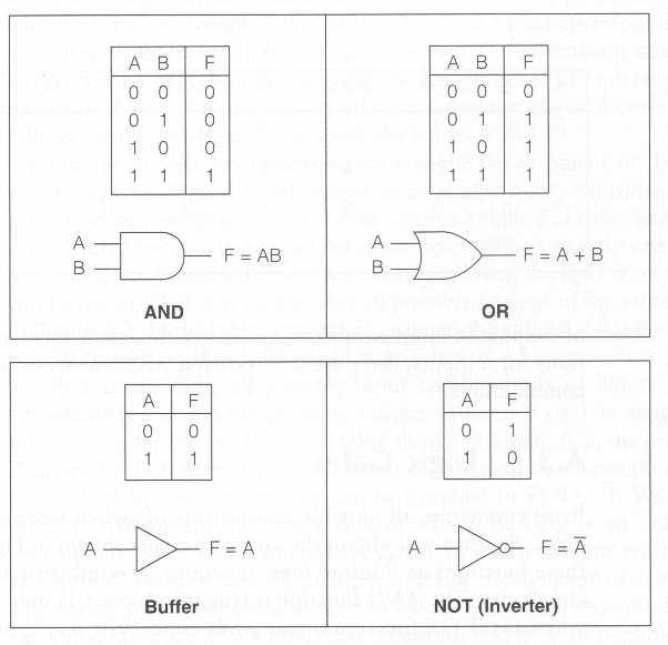
A logic gate is a physical device that implements a simple Boolean function. Standard denotations for the AND, OR and NOT gates are shown in the following picture.
The output of the AND gate is true if an only if both its inputs are true. The output of the OR gate is true when both of its inputs are true, and is false otherwise. The buffer simply copies its input to its outputs. It serves an important practical role as an amplifier. The NOT gate (also called inverter) just inverts the input signal.
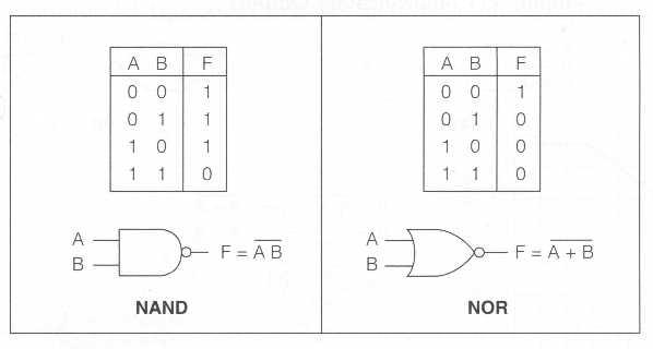
The circle at the output of a gate denotes the complement operation. Thus, the following two gates produce the NAND and NOR functions, defined as
respectively.
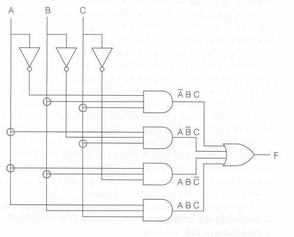
The AND, NOR and NOR gates can be used for drawing circuit diagrams of logic devices. For example, consider the majority function defined by
| A B C | F |
|---|---|
| 0 0 0 0 0 1 0 1 0 0 1 1 1 0 0 1 0 1 1 1 0 1 1 1 |
0 0 0 1 0 1 1 1 |
Represent it in the SOP form:
| F = (¬A·B·C) ∨ (A·¬B·C) ∨ (A·B·¬C) ∨ (A·B·C) |
Then it can be implemented as